


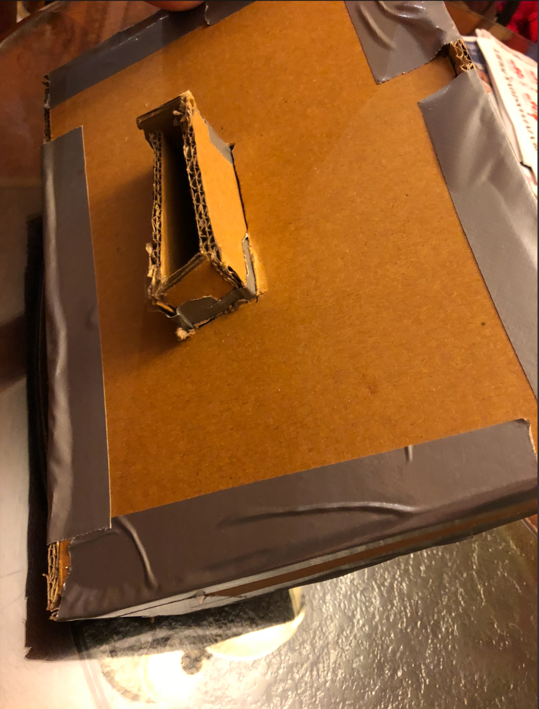
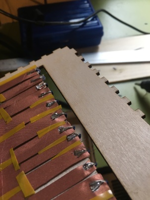
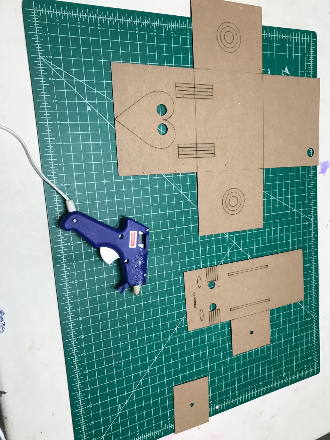
Figure 1
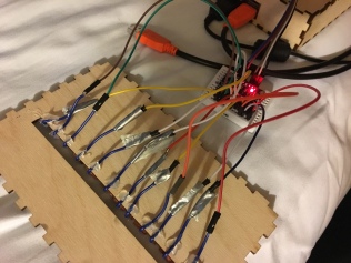
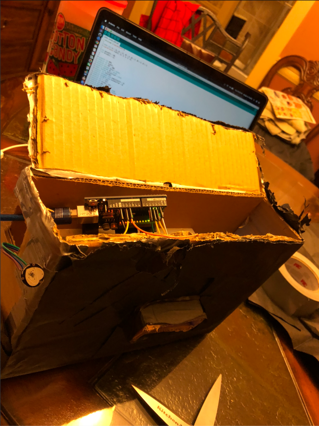 Figure 2
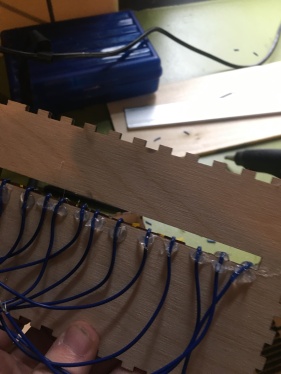
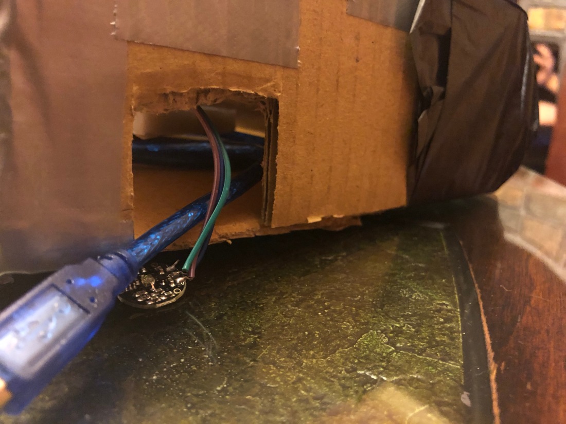 Figure 3
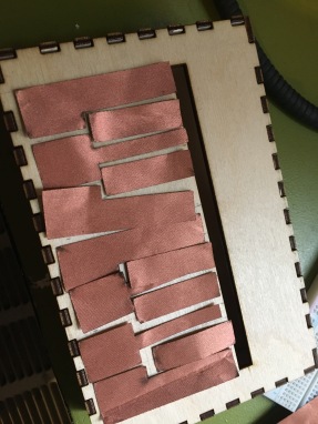
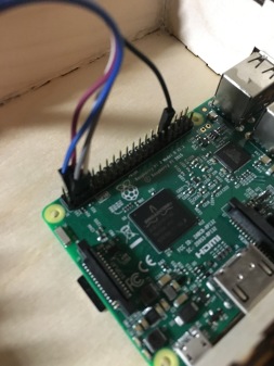
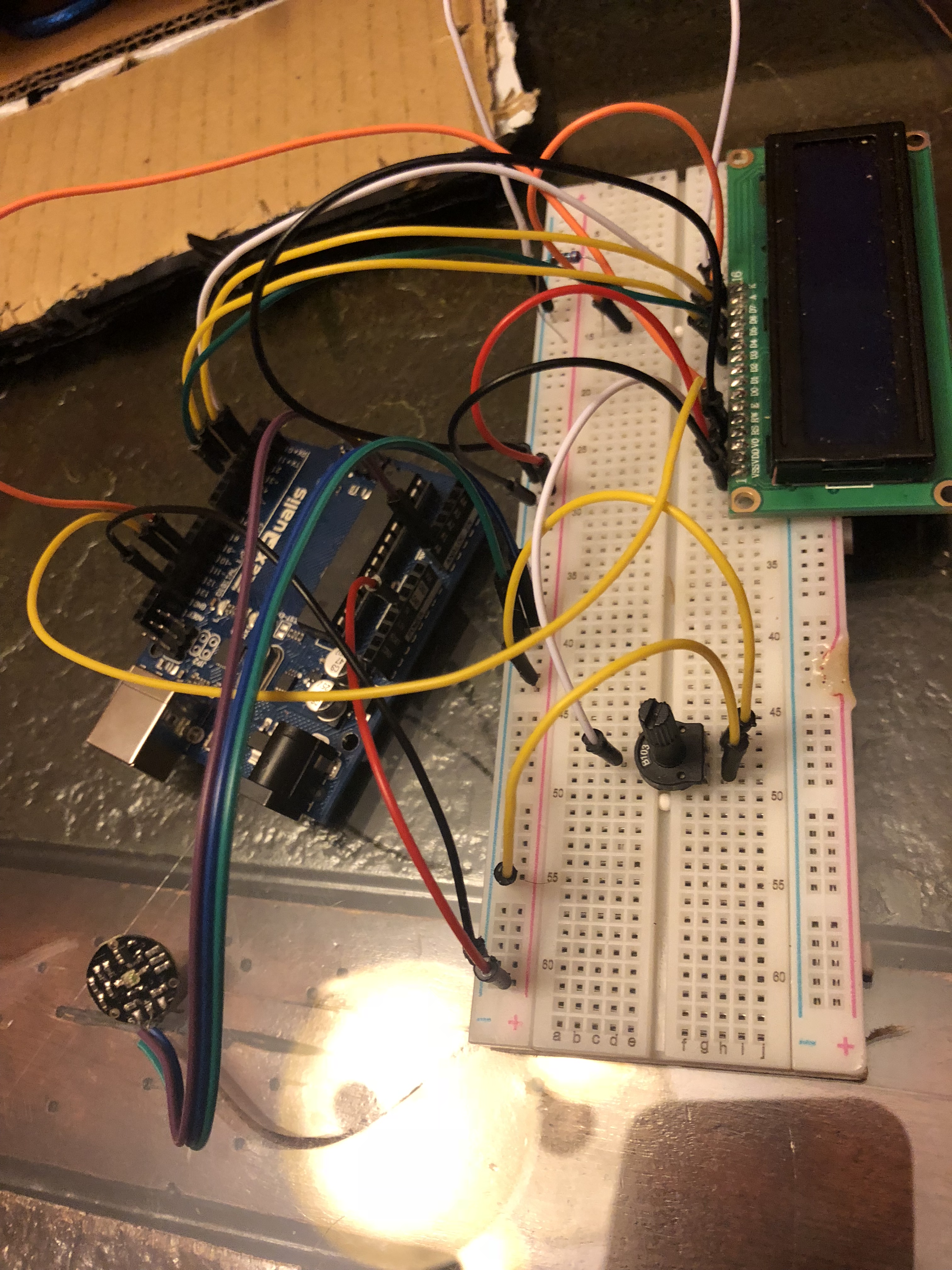 Figure 4
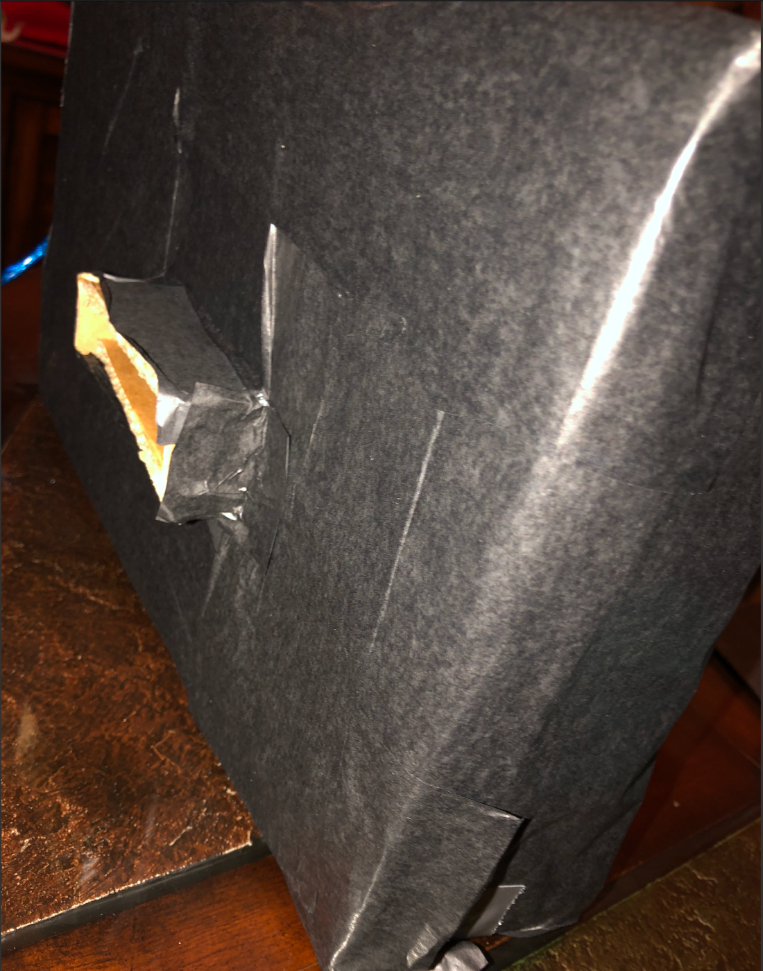 Figure 5
Code:
#include <LiquidCrystal.h>
const int rs = 12, en = 11, d4 = 5, d5 = 4, d6 = 3, d7 = 2;
LiquidCrystal lcd(12, 11, 5, 4, 3, 2);
int pulsePin = A0;
int blinkPin = 13;
volatile int BPM;
volatile int Signal;
volatile int IBI = 600;
volatile boolean Pulse = false;
volatile boolean QS = false;
static boolean serialVisual = true;
volatile int rate[10];
volatile unsigned long sampleCounter = 0;
volatile unsigned long lastBeatTime = 0;
volatile int P = 512;
volatile int T = 512;
volatile int thresh = 525;
volatile int amp = 100;
volatile boolean firstBeat = true;
volatile boolean secondBeat = false;
void setup()
{
pinMode(blinkPin, OUTPUT);
Serial.begin(115200);
interruptSetup();
lcd.begin(16, 2);
lcd.clear();
}
void loop()
{
serialOutput();
if (QS == true)
{
serialOutputWhenBeatHappens();
QS = false;
}
delay(20);
}
void interruptSetup()
{
TCCR2A = 0x02;
TCCR2B = 0x06;
OCR2A = 0X7C;
TIMSK2 = 0x02;
sei();
}
void serialOutput()
{
if (serialVisual == true)
{
arduinoSerialMonitorVisual(‘-‘, Signal);
}
else
{
sendDataToSerial(‘S’, Signal);
}
}
void serialOutputWhenBeatHappens()
{
if (serialVisual == true)
{
Serial.print(” Heart-Beat Found “);
Serial.print(“BPM: “);
Serial.println(BPM);
lcd.print(“Heart-Beat Found “);
lcd.setCursor(1, 1);
lcd.print(“BPM: “);
lcd.setCursor(5, 1);
lcd.print(BPM);
delay(300);
lcd.clear();
}
else
{
sendDataToSerial(‘B’, BPM);
sendDataToSerial(‘Q’, IBI);
}
}
// this is making me cry why is this so hardbkjZSDCDBJKSZDjkndcjknszdjnkzdbcarv;rejkn
void arduinoSerialMonitorVisual(char symbol, int data )
{
const int sensorMin = 0;
const int sensorMax = 1024;
int sensorReading = data;
int range = map(sensorReading, sensorMin, sensorMax, 0, 11);
}
void sendDataToSerial(char symbol, int data )
{
Serial.print(symbol);
Serial.println(data);
}
ISR(TIMER2_COMPA_vect)
{
cli();
Signal = analogRead(pulsePin);
sampleCounter += 2;
int N = sampleCounter – lastBeatTime;
if (Signal < thresh && N > (IBI / 5) * 3)
{
if (Signal < T)
{
T = Signal;
}
}
if (Signal > thresh && Signal > P)
{
P = Signal;
}
if (N > 250)
{
if ( (Signal > thresh) && (Pulse == false) && (N > (IBI / 5) * 3) )
{
Pulse = true;
digitalWrite(blinkPin, HIGH);
IBI = sampleCounter – lastBeatTime;
lastBeatTime = sampleCounter;
if (secondBeat)
{
secondBeat = false;
for (int i = 0; i <= 9; i++)
{
rate[i] = IBI;
}
}
if (firstBeat)
{
firstBeat = false;
secondBeat = true;
sei();
return;
}
word runningTotal = 0;
for (int i = 0; i <= 8; i++)
{
rate[i] = rate[i + 1];
runningTotal += rate[i];
}
rate[9] = IBI;
runningTotal += rate[9];
runningTotal /= 10;
BPM = 60000 / runningTotal;
QS = true;
}
}
if (Signal < thresh && Pulse == true)
{
digitalWrite(blinkPin, LOW);
Pulse = false;
amp = P – T;
thresh = amp / 2 + T;
P = thresh;
T = thresh;
}
if (N > 2500)
{
thresh = 512;
P = 512;
T = 512;
lastBeatTime = sampleCounter;
firstBeat = true;
secondBeat = false;
}
sei();
}
#define trigPin 7
#define echoPin 6
#define led 13
#define led2 12
#define led3 11
#define led4 10
#define led5 9
#define led6 8
#define buzzer 3
int sound = 250;
void setup() {
// put your setup code here, to run once:
Serial.begin (9600);
pinMode(trigPin, OUTPUT);
pinMode(echoPin, INPUT);
pinMode(led, OUTPUT);
pinMode(led2, OUTPUT);
pinMode(led3, OUTPUT);
pinMode(led4, OUTPUT);
pinMode(led5, OUTPUT);
pinMode(led6, OUTPUT);
pinMode(buzzer, OUTPUT);
}
void loop() {
// put your main code here, to run repeatedly:
long duration, distance;
digitalWrite(trigPin, LOW);
delayMicroseconds(2);
digitalWrite(trigPin, HIGH);
delayMicroseconds(10);
digitalWrite(trigPin, LOW);
duration = pulseIn(echoPin, HIGH);
distance = (duration/2) / 29.1;
if (distance <= 30) {
digitalWrite(led, HIGH);
sound = 250;
}
else {
digitalWrite(led,LOW);
}
if (distance < 25) {
digitalWrite(led2, HIGH);
sound = 260;
}
else {
digitalWrite(led2, LOW);
}
if (distance < 20) {
digitalWrite(led3, HIGH);
sound = 270;
}
else {
digitalWrite(led3, LOW);
}
if (distance < 15) {
digitalWrite(led4, HIGH);
sound = 280;
}
else {
digitalWrite(led4,LOW);
}
if (distance < 10) {
digitalWrite(led5, HIGH);
sound = 290;
}
else {
digitalWrite(led5,LOW);
}
if (distance < 5) {
digitalWrite(led6, HIGH);
sound = 300;
}
else {
digitalWrite(led6,LOW);
}
if (distance > 30 || distance <= 0){
Serial.println(“Out of range”);
noTone(buzzer);
}
else {
Serial.print(distance);
Serial.println(” cm”);
tone(buzzer, sound);
}
delay(500);
}
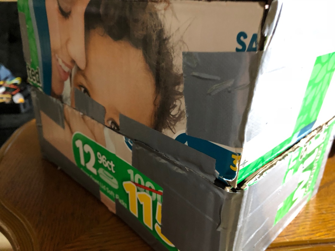
Figure 1
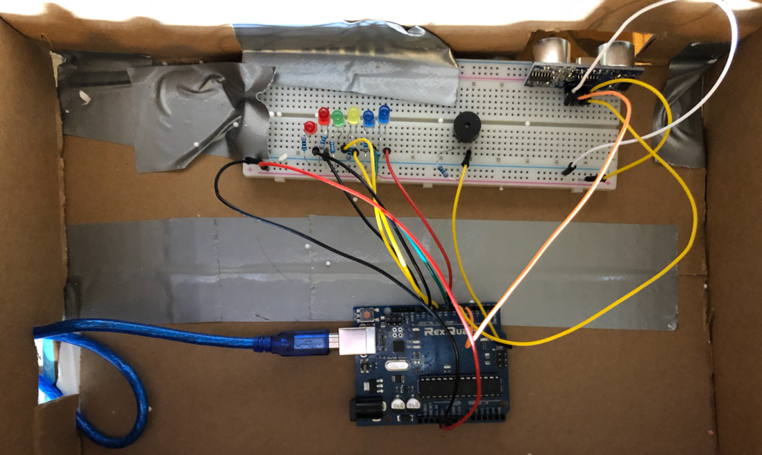
Figure 2
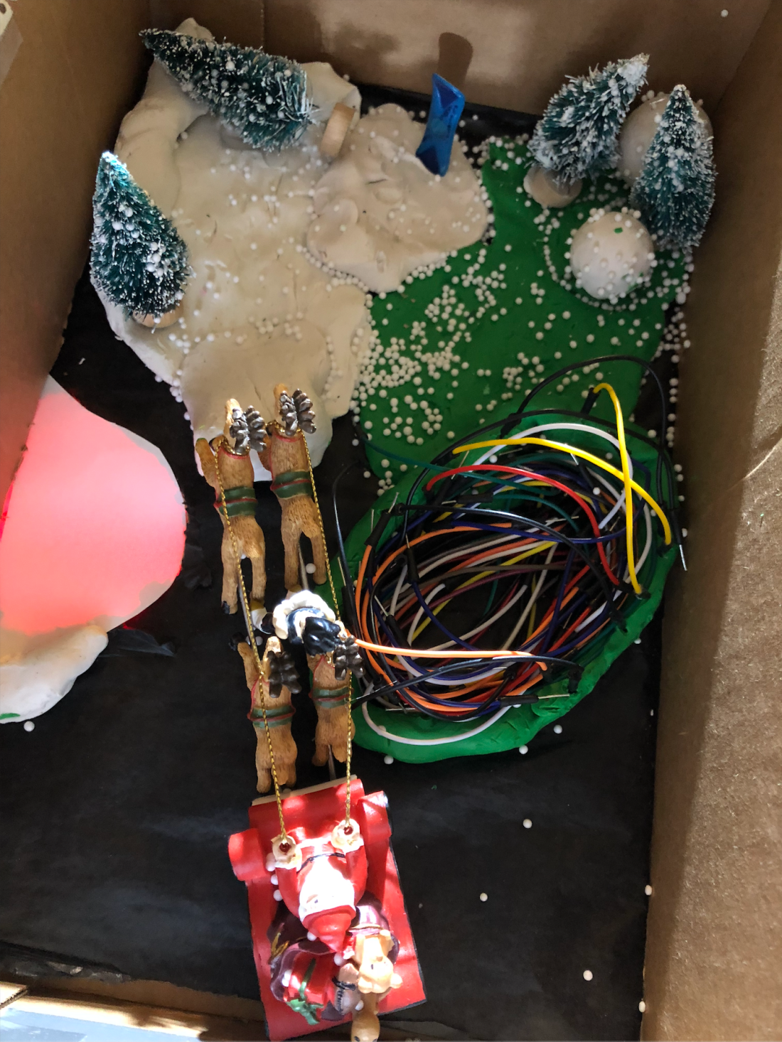
Figure 3
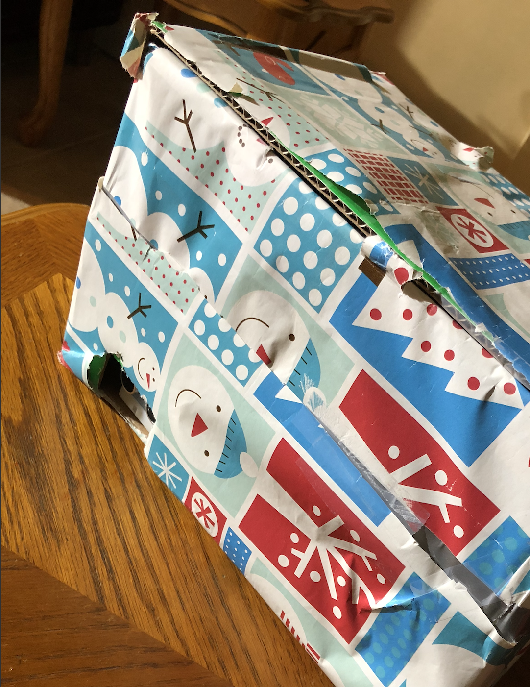
Figure 4
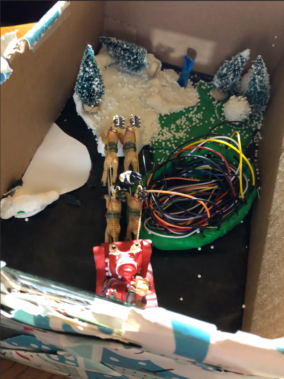
Figure 5
int trigPin = 11; // Trigger
int echoPin = 12; // Echo
long duration, cm, inches;
int R = 9;
void setup() {
//Serial Port begin
Serial.begin (9600);
//Define inputs and outputs
pinMode(trigPin, OUTPUT);
pinMode(echoPin, INPUT);
pinMode(R, OUTPUT);
}
void loop() {
// The sensor is triggered by a HIGH pulse of 10 or more microseconds.
// Give a short LOW pulse beforehand to ensure a clean HIGH pulse:
digitalWrite(trigPin, LOW);
delayMicroseconds(5);
digitalWrite(trigPin, HIGH);
delayMicroseconds(10);
digitalWrite(trigPin, LOW);
// Read the signal from the sensor: a HIGH pulse whose
// duration is the time (in microseconds) from the sending
// of the ping to the reception of its echo off of an object.
pinMode(echoPin, INPUT);
duration = pulseIn(echoPin, HIGH);
// Convert the time into a distan ce
cm = (duration / 2) / 29.1; // Divide by 29.1 or multiply by 0.0343
inches = (duration / 2) / 74; // Divide by 74 or multiply by 0.0135
if (cm > 0 && cm <= 20) { //distcance is greater than 0 and less than 20cm
Serial.print(“LED”);
digitalWrite(R, HIGH); //red led is on // turn the LED on (HIGH is the voltage level)
delay(500); // wait for a second
digitalWrite(R, LOW); // turn the LED off by making the voltage LOW
delay(500); // wait for a second
} else if (cm > 20 && cm <= 80) { //distcance is greater than 20 and less than 80cm
digitalWrite(R, LOW); //red led is off
}
Serial.print(inches);
Serial.print(“in, “);
Serial.print(cm);
Serial.print(“cm”);
Serial.println();
delay(250);


For this project I’ve made a keyboard that uses capacitive touch as an input method. It boasts an impressive 12 keys so you can play almost an entire chromatic scale (MPR121 doesn’t have a 13th pin). This project uses software called Sonic Pi that is essentially a program that allows you to play sounds with code. I referenced this project to figure out how to get this to work so I will link it here if you want to see https://rbnrpi.wordpress.com/project-list/a-musical-12-tone-alarm-for-the-raspberry-pi-part-1/12-input-touch-keyboard-for-sonic-pi/
Here is what I made it with:
As you can see, instead of arduino, this project uses a Raspberry Pi. Pi has a lot more options when it comes to producing sound compared to using the digital pins on an arduino.
Step 1: Building the thing.
I used this website http://www.makercase.com/ to laser cut myself a box that was 6.25″ x 4″. I then cut more holes into it so I could poke wires through the top. Then I laser cut out all 12 keys and just kinda taped them into place.
Step 2: Wiring stuff
This was the most annoying part to do since I didn’t have enough solder to do it correctly.
First I soldered braided wires directly onto each key. That was a nice mistake because now the other end of the wire wont fit into the breadboard with the mpr121. To fix this I just duck taped jumper wires onto each key’s wire so I could make a “solid” connection to the sensor. The order of wiring the keys to the sensor starts with the leftmost key at pin 0 and just goes up to pin 11.
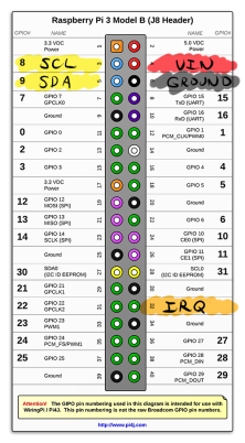
Connecting the MPR121 to the Pi is also annoying because they don’t label any of the pins. Lucky for you I looked everything up and labeled it myself.
Step 3: the Pi
Okay now you have to figure out how to get this thing running. First you have to go to https://www.raspberrypi.org/downloads/raspbian/ and download Raspbian Stretch with recommend software. Once you download that you need to get it on a microSD card using disc image software. I just used something called rufus https://rufus.ie/en_IE.html
To get the sensor to actually work with Pi there are a few steps you need to do. https://learn.adafruit.com/mpr121-capacitive-touch-sensor-on-raspberry-pi-and-beaglebone-black/software You can check this link for detailed instructions.
First you need to edit the /boot/config.txt and add this line to the bottom so the mpr121 actually works.
dtoverlay=i2c-bcm2708
After that install python3 by typing this into the terminal.
sudo apt-get update
sudo apt-get install build-essential python3-dev python3-smbus python3-pip git
cd ~
git clone https://github.com/adfruit/Adafruit_Python_MPR121
sudo python3 setup.py install
Now you need to save this as a python file. This is used so the mpr121 can interface with the software we are using.
#!/usr/bin/env python3

#driver for 12 pad touch keys and ps3 wireless controller by Robin Newman
#April 2018
#uses library for Adafruit MPR121 board

# Copyright (c) 2014 Adafruit Industries
# Author: Tony DiCola
#
# Permission is hereby granted, free of charge, to any person obtaining a copy
# of this software and associated documentation files (the "Software"), to deal
# in the Software without restriction, including without limitation the rights
# to use, copy, modify, merge, publish, distribute, sublicense, and/or sell
# copies of the Software, and to permit persons to whom the Software is
# furnished to do so, subject to the following conditions:
#
# The above copyright notice and this permission notice shall be included in
# all copies or substantial portions of the Software.
#
# THE SOFTWARE IS PROVIDED "AS IS", WITHOUT WARRANTY OF ANY KIND, EXPRESS OR
# IMPLIED, INCLUDING BUT NOT LIMITED TO THE WARRANTIES OF MERCHANTABILITY,
# FITNESS FOR A PARTICULAR PURPOSE AND NONINFRINGEMENT. IN NO EVENT SHALL THE
# AUTHORS OR COPYRIGHT HOLDERS BE LIABLE FOR ANY CLAIM, DAMAGES OR OTHER
# LIABILITY, WHETHER IN AN ACTION OF CONTRACT, TORT OR OTHERWISE, ARISING FROM,
# OUT OF OR IN CONNECTION WITH THE SOFTWARE OR THE USE OR OTHER DEALINGS IN
# THE SOFTWARE.
# NB Install Adafruit Library and python-osc library before use
import sys
import time
import pygame

import Adafruit_MPR121.MPR121 as MPR121

from pythonosc import osc_message_builder #add library for OSC support
from pythonosc import udp_client
import argparse
pygame.display.init()
##### uncomment next three lines to add joystick support
#pygame.joystick.init() #add support for PS3 controller
#ps3=pygame.joystick.Joystick(0)
#ps3.init()

def control(spip): #This is called once __main__ has set up the Sonic Pi ip address
gate = 0.1 #dead area used for PS3 joysticks
sender=udp_client.SimpleUDPClient(spip,4559) #set up OSC link to Sonic Pi


print('Adafruit MPR121 Capacitive Touch keypads')

# Create MPR121 instance.
cap = MPR121.MPR121()

# Initialize communication with MPR121 using default I2C bus of device, and
# default I2C address (0x5A). On BeagleBone Black will default to I2C bus 0.
if not cap.begin():
print('Error initializing MPR121. Check your wiring!')
sys.exit(1)

# Alternatively, specify a custom I2C address such as 0x5B (ADDR tied to 3.3V),
# 0x5C (ADDR tied to SDA), or 0x5D (ADDR tied to SCL).
#cap.begin(address=0x5B)

# Also you can specify an optional I2C bus with the bus keyword parameter.
#cap.begin(busnum=1)

pygame.init()


# Main loop to print a message every time a pin is touched.
print('Press Ctrl-C to quit.')
last_touched = cap.touched()
while True:
try:
current_touched = cap.touched()
# Check each pin's last and current state to see if it was pressed or released.
for i in range(12):
# Each pin is represented by a bit in the touched value. A value of 1
# means the pin is being touched, and 0 means it is not being touched.
pin_bit = 1 << i
# First check if transitioned from not touched to touched.
if current_touched & pin_bit and not last_touched & pin_bit:
print('{0} touched!'.format(i))
print("/key"+str(i)+',1')
sender.send_message('/key'+str(i) ,1)
if not current_touched & pin_bit and last_touched & pin_bit:
print('{0} released!'.format(i))
print('/key'+str(i)+',0')
sender.send_message('/key'+str(i) ,0)


# Update last state and wait a short period before repeating.
last_touched = current_touched
time.sleep(0.1)

except KeyboardInterrupt:
print("\nExiting")
sys.exit()

if __name__=="__main__":
parser = argparse.ArgumentParser() #setup retrieving arg (if any) for --sp
parser.add_argument("--sp",
default="127.0.0.1", help="The ip on which Sonic Pi listens")
args = parser.parse_args()
spip=args.sp
print("Sonic Pi on ip",spip)
control(spip)
Basically it will send events to Sonic Pi whenever a key is pressed so the code can respond to it.
Open up Sonic Pi, which is already installed, and put this code in.
#written by Robin Newman, April 2018
#moddified by Max Kawula

#the following function detects value of wild card in osc address
define:parse_sync_address do |address|
v= get_event(address).to_s.split(",")[6]
if v != nil
return v[3..-2].split("/")
else
return ["error"]
end
end

use_synth :piano #set initial synth
set :base,60 #set initial octave base note

live_loop :getkey do
use_real_time
b = sync "/osc/key*" #detect osc messages from ANY key using wild card *
if b[0] == 1 #if the key has been pressed
res = parse_sync_address "/osc/key*" #decode wild card value
puts "Decoded address information is",res
key = res[1][3..-1].to_i #extract key from res list and convert to integer
puts "key pressed was",key
if key<11
scaleOffset=[1,2,3,4,5,6,7,8,9,10,11,12]
play note get(:base) + scaleOffset[key]

end
end
end
Hit run and the keyboard should work. Here is a video of me playing it.
You might notice that there is a noticeable amount of latency every time I hit a key. That is because the software I’m using is really slow on Pi. The only work around on this is to send the OSC events to a remote computer running sonic pi and it should eliminate that horrible delay.
2 page paper below:
For my wearable/interactive project I made a midi controller. Thanks to a midi controller I can take controls in an audio workstation and change them with the knobs. In this project, I am using Ableton, which has full Arduino support.
The layout of the whole thing is pretty simple, it’s basically knobs controlling stuff inside a program, therefore the code is also simple. The code is taken from the Arduino examples, it’s called Standart Firmata in the Firmata section.
Part List
Instructions
on Kit from Ableton.com
Now you can map any control you want to any knob.
The idea was taken from Ask Audio.


Video
https://drive.google.com/file/d/1KQ3fJ7iB8XMFwy2QcVxyUZ-5ce8y7PZu/view?usp=sharing
Final Paper
https://docs.google.com/document/d/1vU-2Nx-ig0ZyoE-vJsLP1J5_5KwEvZEXVwSuimsj-cM/edit?usp=sharing
Materials
How to Build It
(All wiring will be detailed in the wiring section that comes after this)
Wiring
Code
//Used several different codes to help piece together, including bits from the MPR121 class example, and from an online drum machine tutorial by some guy with a frog avatar
//Below are for SD card, using the SimpleSDAudio library which needs to be downloaded from the internet
#include <sd_l0.h>
#include <sd_l1.h>
#include <sd_l2.h>
#include <SimpleSDAudio.h>
#include <SimpleSDAudioDefs.h>
//below are for the MPR121touch sensor
#include <Wire.h>
#include “Adafruit_MPR121.h”
#ifndef _BV
#define _BV(bit) (1 << (bit))
#endif
// You can have up to 4 on one i2c bus but one is enough for testing!
Adafruit_MPR121 cap = Adafruit_MPR121(); //sensor 1 – drums
Adafruit_MPR121 cap2 = Adafruit_MPR121(); //sensor 2 – keyboard
// Keeps track of the last pins touched
// so we know when buttons are ‘released’
//sensor 1 – drums
uint16_t lasttouched = 0;
uint16_t currtouched = 0;
// Keeps track of the last pins touched
// so we know when buttons are ‘released’
//sensor 2 – keys
uint16_t lasttouched2 = 0;
uint16_t currtouched2 = 0;
//Code of MPR121 taken from class example
void setup()
{
Serial.begin(9600);
tone(9, 200, 30);//play startup sound
Serial.println(F(“startup Sound”));
delay (1000);
// SD card initialization
SdPlay.setSDCSPin(10); // chip select
SdPlay.init(SSDA_MODE_FULLRATE | SSDA_MODE_MONO | SSDA_MODE_AUTOWORKER);
Serial.println(F(“sd ready”));
// Capactive touch sensor initialization
Serial.println(F(“Adafruit MPR121 Capacitive Touch sensor test”));
// Default address is 0x5A, if tied to 3.3V its 0x5B
// If tied to SDA its 0x5C and if SCL then 0x5D
if (!cap.begin(0x5A)) {
Serial.println(F(“MPR121 not found, check wiring?”));
while (1);
}
Serial.println(“MPR121 found!”);
//to sense MPR sensor number 2, use different address. Tie ADR pin to 3.3V
if (!cap2.begin(0x5B)) {
Serial.println(F(“MPR121 number 2 not found, check wiring?”));
while (1);
}
Serial.println(F(“MPR121 Dos found!”));
}
void loop()
{
currtouched = cap.touched(); //sets variables that store what pins are currently touched for each touch sensor
currtouched2 = cap2.touched();
//hook up speaker to pin 9, just like before on flannel
/*MPR121 Code
Code works by sensing if currently touched pin = corresponding pin. As long as the pin was not pressed the last time
through the loop, the sound will play. This prevents the possility of holding the pin and having the sound continuously play.
Cannot do this because since the programs loops so fast (for the sake of fastest response to touch possible), the sounds end up
being too fast when playing continously and sound like a crazy machine rather than an instrument.
*/
if ((currtouched & _BV(8)) && !(lasttouched & _BV(8))) {
SdPlay.setFile(“snare001.raw”); //sets up snare tone to run when called
SdPlay.play(); //plays snare sound
Serial.print(F(“snare sound playing”)); //F stores the string in flash memory, had to do this to save space
Serial.println();
}
else if ((currtouched & _BV(9)) && !(lasttouched & _BV(9)) && !(currtouched & _BV(8)) && !(currtouched & _BV(3))) { //code only executes if snare isn’t hit. Snare has priority.
SdPlay.setFile(“hat001.raw”); //sets up hi-hat tone to run when called
SdPlay.play();
Serial.print(F(“hi-hat sound playing”));
Serial.println();
}
if ((currtouched & _BV(3)) && !(lasttouched & _BV(3))) {
// play the bass drum sound if the pedal is pressed, and the touch pad is held
SdPlay.setFile(“tom.raw”); //sets up bass drum tone to run when called
SdPlay.play();
Serial.print(F(“bass drum sound playing”));
Serial.println();
}
if ((currtouched & _BV(4)) && !(lasttouched & _BV(4))) {
// play the crash cymbal sound
SdPlay.setFile(“crash001.raw”); //sets up bass drum tone to run when called
SdPlay.play();
Serial.print(F(“crash sound playing”));
Serial.println();
}
//All sounds from sensor 2 – Keys
if ((currtouched2 & _BV(0)) && !(lasttouched2 & _BV(0))) {
SdPlay.setFile(“a4.raw”); //sets up A note to run when called
SdPlay.play();
Serial.print(F(“A note playing”));
Serial.println();
}
if ((currtouched2 & _BV(1)) && !(lasttouched2 & _BV(1))) {
SdPlay.setFile(“a#4.raw”); //sets up A# note to run when called
SdPlay.play();
Serial.print(F(“A sharp note playing”));
Serial.println();
}
if ((currtouched2 & _BV(2)) && !(lasttouched2 & _BV(2))) {
SdPlay.setFile(“b4.raw”); //sets up B note to run when called
SdPlay.play();
Serial.print(F(“B note playing”));
Serial.println();
}
if ((currtouched2 & _BV(3)) && !(lasttouched2 & _BV(3))) {
SdPlay.setFile(“c5.raw”); //sets up C note to run when called
SdPlay.play();
Serial.print(F(“C note playing”));
Serial.println();
}
if ((currtouched2 & _BV(4)) && !(lasttouched2 & _BV(4))) {
SdPlay.setFile(“c#5.raw”); //sets up C# note to run when called
SdPlay.play();
Serial.print(F(“C# note playing”));
Serial.println();
}
if ((currtouched2 & _BV(5)) && !(lasttouched2 & _BV(5))) {
SdPlay.setFile(“d5.raw”); //sets up D note to run when called
SdPlay.play();
Serial.print(F(“D note playing”));
Serial.println();
}
if ((currtouched2 & _BV(6)) && !(lasttouched2 & _BV(6))) {
SdPlay.setFile(“d#5.raw”); //sets up D# note to run when called
SdPlay.play();
Serial.print(F(“D# note playing”));
Serial.println();
}
if ((currtouched2 & _BV(7)) && !(lasttouched2 & _BV(7))) {
SdPlay.setFile(“e5.raw”); //sets up E note to run when called
SdPlay.play();
Serial.print(F(“E note playing”));
Serial.println();
}
if ((currtouched2 & _BV(8)) && !(lasttouched2 & _BV(8))) {
SdPlay.setFile(“f5.raw”); //sets up F note to run when called
SdPlay.play();
Serial.print(F(“F note playing”));
Serial.println();
}
if ((currtouched2 & _BV(9)) && !(lasttouched2 & _BV(9))) {
SdPlay.setFile(“f#5.raw”); //sets up F# note to run when called
SdPlay.play();
Serial.print(F(“F# note playing”));
Serial.println();
}
if ((currtouched2 & _BV(10)) && !(lasttouched2 & _BV(10))) {
SdPlay.setFile(“g5.raw”); //sets up G note to run when called
SdPlay.play();
Serial.print(F(“G note playing”));
Serial.println();
}
if ((currtouched2 & _BV(11)) && !(lasttouched2 & _BV(11))) {
SdPlay.setFile(“g#5.raw”); //sets up G# note to run when called
SdPlay.play();
Serial.print(F(“G# note playing”));
Serial.println();
}
// reset our state for both Capacitive Touch Sensors
lasttouched = currtouched;
lasttouched2 = currtouched2;
delay(20); //delays just enough so that the sounds don’t happen too fast. Without this, it is TOO responsive and sounds messy
// Also, I found that I cannot go beyond, 43% of dynamic memory, or all sounds from SD card stop working.
// Could be possible that this aftermarket Arduino board does not have as much memory as the genuine Arduino unit.
}
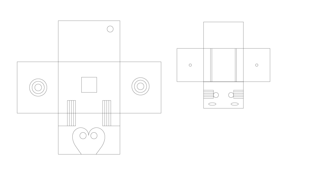
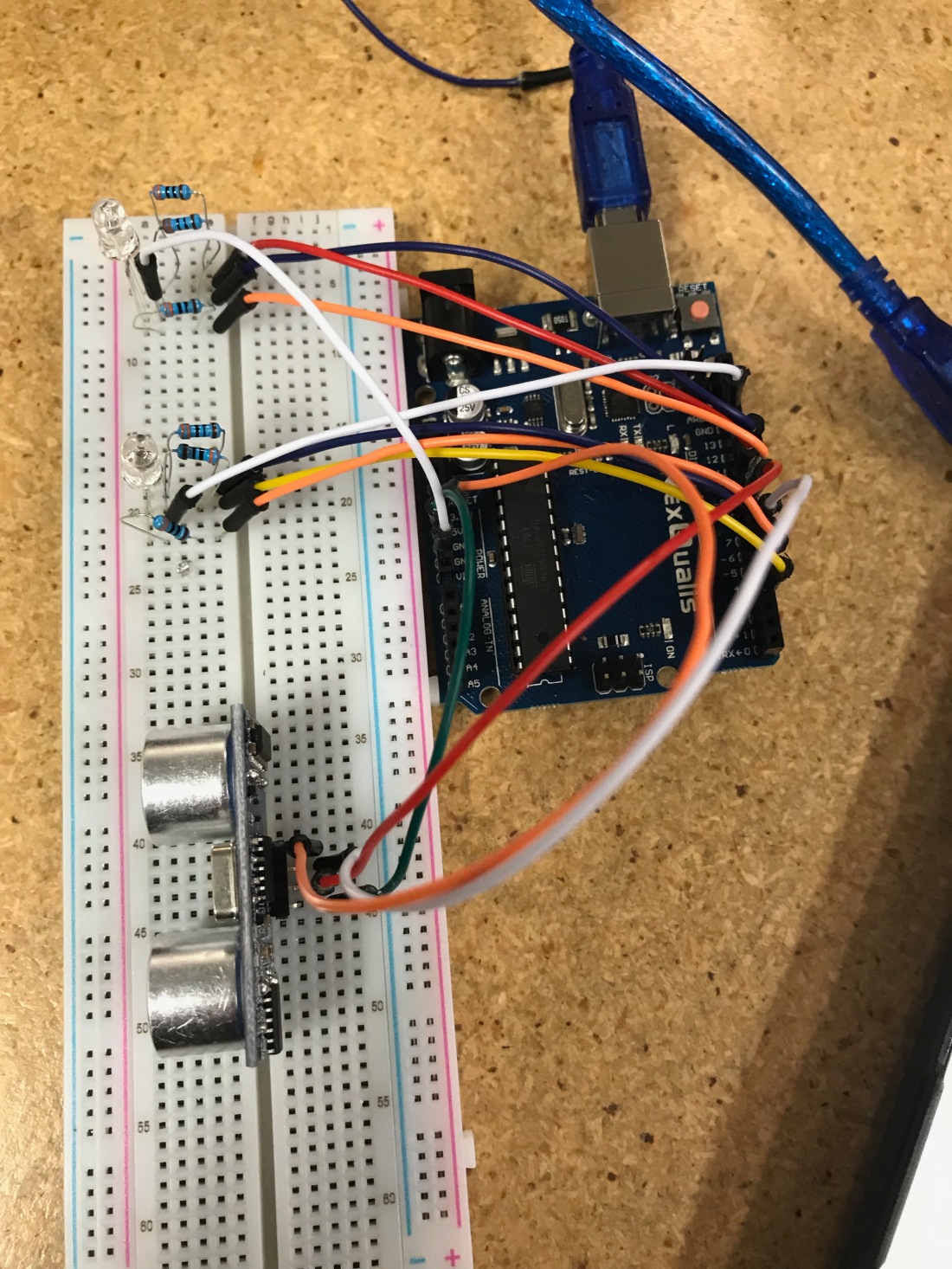
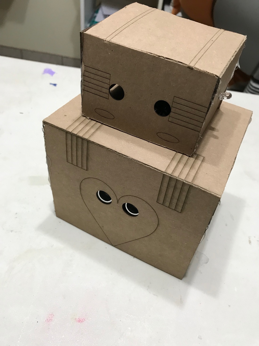
Cuddle Bot is a lonely little robot that needs human interaction. When you get closer to Cuddle Bot, his lights become warmer and brighter. When you go away from him, his lights go off. The idea is to display emotions onto an otherwise lifeless object. We tend to give character and special meaning to the things we own. I know I do this all the time; therefore, I want to bring that aspect to this animated sculpture. It’s as if the human interacting with the bot is giving life to it. We need others to feel complete and that’s what this little guy will show.
Step 1: Connect wires to breadboard to test
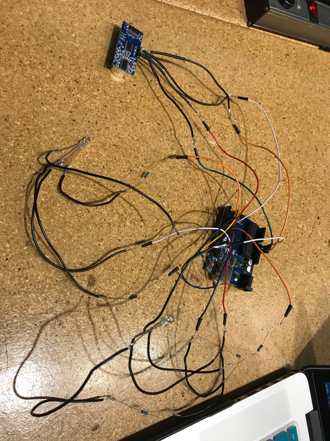
Step 2: If the sensor and lights work together, soder all parts together
Step 3: Construct Bot by sending chipboard to a laser printer to cut
Step 4: Use Exacto knife to score material on parts that will fold
Step 5: Hot Glue the pieces together and finish bot construction
Step 6: Place and tape circuits into the bot as shown
Step 7: Use and enjoy your new buddy
*/
//Sensor//
int trigPin = 7; // Trigger
int echoPin = 8; // Echo
long duration, cm, inches;
int colorValue = 0;
//RGB LEDs//
int redPin = 11;
int greenPin = 10;
int bluePin = 9;
int redPin2 = 3;
int greenPin2 = 6;
int bluePin2 = 5;
void setup() {
//Sensor//
//Serial Port begin
Serial.begin (9600);
//Define inputs and outputs
pinMode(trigPin, OUTPUT);
pinMode(echoPin, INPUT);
//RGB LEDs//
pinMode(redPin, OUTPUT);
pinMode(greenPin, OUTPUT);
pinMode(bluePin, OUTPUT);
pinMode(redPin2, OUTPUT);
pinMode(greenPin2, OUTPUT);
pinMode(bluePin2, OUTPUT);
}
void loop() {
//RGB LEDs//
setColor(colorValue, colorValue / 2, 255); // aqua
//Sensor//
// The sensor is triggered by a HIGH pulse of 10 or more microseconds.
// Give a short LOW pulse beforehand to ensure a clean HIGH pulse:
digitalWrite(trigPin, LOW);
delayMicroseconds(5);
digitalWrite(trigPin, HIGH);
delayMicroseconds(10);
digitalWrite(trigPin, LOW);
// Read the signal from the sensor: a HIGH pulse whose
// duration is the time (in microseconds) from the sending
// of the ping to the reception of its echo off of an object.
pinMode(echoPin, INPUT);
duration = pulseIn(echoPin, HIGH);
// Convert the time into a distance aaa
cm = (duration/2) / 29.1; // Divide by 29.1 or multiply by 0.0343
inches = (duration/2) / 74; // Divide by 74 or multiply by 0.0135
colorValue = map(cm, 0, 90, 0, 255);
Serial.print(inches);
Serial.print(“in, “);
Serial.print(cm);
Serial.print(“cm”);
Serial.println();
delay(250);
}
void setColor(int red, int green, int blue)
{
#ifdef COMMON_ANODE
red = 255 – red;
green = 255 – green;
blue = 255 – blue;
#endif
analogWrite(redPin, red);
analogWrite(greenPin, green);
analogWrite(bluePin, blue);
analogWrite(redPin2, red);
analogWrite(greenPin2, green);
analogWrite(bluePin2, blue);
}
https://drive.google.com/file/d/1pTta6jtTjKQ3jqCe3PYQv_gYmM8y-iwe/view?usp=sharing
This project is a synthesizer. It creates sounds by moving the oscillators which are linked to the knobs. It has also an aux port which is necessary to hear the sounds, speakers are preferred since with headphones it’s harsh to the ears. I wanted to create this project because synthesizers are of my interest, and I always wanted to buy one, but now I have the opportunity to make one, and actually use it outside of school.
Paper: essay
Parts
Part 1
Take your box and find where you want to place your knobs LED, audio jack port and the hole for the AC adapter cable. The potentiometers and led are of preference, but I recommend placing them apart from each other because it will make it easier to solder. As it goes for the other two holes, you should put one on the front of the box and one on the other front, this will make it easier for the AC cord to go out without being tangled with the wires.
Part 2
Mark the sports with a white sharpie or anything that will give you a sense of directions. Choose the appropriate size for the drill and drill the holes. Do this carefully because once you drill there is no going back.
Part 3
Now it’s time to figure out the schematic. I have a picture of the schematic linked below. To make things easier take a wire and put one in the 5v socket of the Arduino, the other one in the ground pin. Make sure these wires are longer than the other wires because they are the main wires that everything is going to be hooked up to. The middle pin of the potentiometer goes to the A pins on the Arduino, the other two on opposite sides go 5V and ground. To create a good running circuit, make sure that you connect all 5V wires of the potentiometers together, and then connect only the last one to the main 5V wire, do the same for the ground wires, but do not do this for the A sockets, those go directly to the Arduino
Part 4
Time to connect the aux and LEDs. For the audio jack, one leg will go to pin 3 in the Arduino, and the other one will go to the ground wire, take a look at the pictures for the right way because of the sides of the legs matter.
The LEDs are connected in a simple circuit, connect the two LEDs together with the corresponding leg, and then connect one of them to the 220-ohm resistor. The longer leg goes to the resistor, and the other leg will go to the ground wire.
Part 5
Now you should have a full circuit running, before putting it inside the box, make sure it runs. After that put the potentiometers and the LEDs in the box, disconnected from the Arduino. Once everything is inside you can connect all the wires back.
*A tip to make the LEDs stay without falling is to fold the legs.
PArt 6
Now that everything is connected, run the ac wire in the hole and close the box. Plug in the AC adapter. If the LEDs are on that means the circuit works. ALso moving the knobs will trigger the LEDs, so if that happens you know that the circuit works.
Finished result
Now you can plug in the audio jack to a set of speakers and play around with the sounds.
Yay
This project is a synthesizer. It creates sounds by moving the oscillators which are linked to the knobs. It has also an aux port which is necessary to hear the sounds, speakers are preferred since with headphones it’s harsh to the ears. I wanted to create this project because synthesizers are of my interest, and I always wanted to buy one, but now I have the opportunity to make one, and actually use it outside of school.
Part 1
Take your box and find where you want to place your knobs LED, audio jack port and the hole for the AC adapter cable. The potentiometers and led are of preference, but I recommend placing them apart from each other because it will make it easier to solder. As it goes for the other two holes, you should put one on the front of the box and one on the other front, this will make it easier for the AC cord to go out without being tangled with the wires.
Part 2
Mark the sports with a white sharpie or anything that will give you a sense of directions. Choose the appropriate size for the drill and drill the holes. Do this carefully because once you drill there is no going back.
Part 3
Now it’s time to figure out the schematic. I have a picture of the schematic linked below. To make things easier take a wire and put one in the 5v socket of the Arduino, the other one in the ground pin. Make sure these wires are longer than the other wires because they are the main wires that everything is going to be hooked up to. The middle pin of the potentiometer goes to the A pins on the Arduino, the other two on opposite sides go 5V and ground. To create a good running circuit, make sure that you connect all 5V wires of the potentiometers together, and then connect only the last one to the main 5V wire, do the same for the ground wires, but do not do this for the A sockets, those go directly to the Arduino
Part 4
Time to connect the aux and LEDs. For the audio jack, one leg will go to pin 3 in the Arduino, and the other one will go to the ground wire, take a look at the pictures for the right way because of the sides of the legs matter.
The LEDs are connected in a simple circuit, connect the two LEDs together with the corresponding leg, and then connect one of them to the 220-ohm resistor. The longer leg goes to the resistor, and the other leg will go to the ground wire.
Part 5
Now you should have a full circuit running, before putting it inside the box, make sure it runs. After that put the potentiometers and the LEDs in the box, disconnected from the Arduino. Once everything is inside you can connect all the wires back.
*A tip to make the LEDs stay without falling is to fold the legs.
PArt 6
Now that everything is connected, run the ac wire in the hole and close the box. Plug in the AC adapter. If the LEDs are on that means the circuit works. ALso moving the knobs will trigger the LEDs, so if that happens you know that the circuit works.
Finished result
Now you can plug in the audio jack to a set of speakers and play around with the sounds.
Yay
Code and instructions were taken from here.
Pictures
Video: https://drive.google.com/file/d/12UfQ8NYWdu8lXzaBfoubkTqgD9dctlm7/view?usp=sharing
Materials: box, cork, wire, stepper motor, wire, pencil, usb cord, arduino, breadboard, 20 wires, battery, tape, one resistor 330 ohms, button.
Steps:
Final Project: Drawing Machine
This project was fun to work on because we were able to fully experiment with all the content we learned the whole semester. I decided to create a drawing machine because I was interested in the development of an unknown outcome with something I could physically build. I wrote the code for my arduino and set everything up on the breadboard. I used one of the rotating motors so that I could attach a drawing utensil to the rotating piece enabling my pencil or pen to move. I then decided it was a little too easy so I added in a button so when the button is held down, the rotation spins clockwise however when the button is not pressed, the rotation spins counter-clockwise. This adds an element of interaction with the piece; without the button, it would be an autonomous machine. One thing I do enjoy about my project is that it looks much cleaner than it did at the beginning with numerous wires out and about. I find it interesting when a piece of art itself creates something and it is even more exciting when the artist doesn’t even know how the outcome will look. It gives the project a performance art quality which sometimes can make the project more fun to watch or witness. I added a box to conceal all of the unfinished looking parts and cut out holes for where things needed to come out of the box. I suppose it would look better if it were painted or one solid color box.
If I had to do the project over and improve it somehow, I would want to figure out how to eliminate the disruption the blue usb cord creates. Because there is an interruption in the circular movement the pencil makes, the project seems less impressive somehow. Then again, the disruption adds to the unknown outcome of what will happen when the pencil is blocked. Another element I would like to add is a different angle rotation. Instead of having it stay stagnant I would enjoy figuring out how I could alter the movement even further and add a vertical spin along with the circular revolution. Going even further, I wonder if eventually I could figure out to create a drawing machine that could actually draw a specific image, word, pattern, etc. I think what I have is a good basis to start at but I could turn it into so much more. I think I would also like to change the button. If I didn’t have to hold down the button, then my finger would not get in the way of the rotating pencil. If I could change it now I would press it once and it would rotate in one direction until I press the button again and It switches directions and so on. I might also consider changing the box it is in and attempt to make it more compact than it looks now.
My original idea for the final project was to sculpt an anthropomorphic figure in two different positions and have two different colored LEDs lining the person in the two separate positions. My idea was that I would turn a knob one way and it would light the sculpture up in one position with one color of lights, and then I would turn the knob the other direction and the sculpture would light up in the other color of lights and it would be in the second position I had arranged them in. This seemed more difficult because I would have to get more LEDs as well as figuring out if I wanted the sculpture three dimensional or two dimensional on paper or something.
I imagine that I could make a combination of my two ideas somehow. I could sculpt a figure and then have them hold the drawing utensil and they would be revolving and creating the unknown outcome. That however eliminates the interactive quality which may be my favorite element. I think the greatest part about this project in general is having the limitless ability to create with the arduino. I’m so grateful to have been introduced to the arduino because the arts are only growing with technology, expanding beyond what we know now. There are so many things you can make with the arduino and there are already so many projects online to use it for. It was also fun to hook up the wires in the correct places to the breadboard and arduino for this project because I realized I now know what goes where and feel confident in how electrical circuits work.


Code for Processing:
Created 11 Mar. 2007
Modified 30 Nov. 2009
by Tom Igoe
*/
#include <Stepper.h>
const int buttonPin = 2; // the number of the pushbutton pin
const int stepsPerRevolution = 200; // change this to fit the number of steps per revolution
// for your motor
int buttonState = 0;
// initialize the stepper library on pins 8 through 11:
Stepper myStepper(stepsPerRevolution, 8, 9, 10, 11);
void setup() {
// initialize the pushbutton pin as an input:
pinMode(buttonPin, INPUT);
// set the speed at 60 rpm:
myStepper.setSpeed(180);
// initialize the serial port:
Serial.begin(9600);
}
void loop() {
// read the state of the pushbutton value:
buttonState = digitalRead(buttonPin);
if (buttonState == HIGH) {
// step one revolution in one direction:
Serial.println(“clockwise”);
myStepper.step(stepsPerRevolution);
//delay(500);
} else {
// step one revolution in the other direction:
Serial.println(“counterclockwise”);
myStepper.step(-stepsPerRevolution);
//delay(500);
}
}
